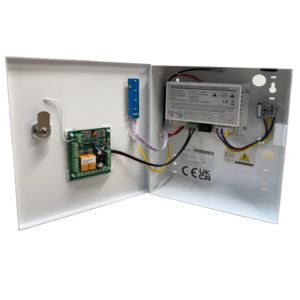
WCRXPCB Disabled Toilet System PCB Control Board
£99.48 ex VAT
New improved disabled toilet locking system controller, allowing radio or wireless touch switches.
Designed specifically for accessible toilet installations, this compact PCB offers reliable control for our toilet door locking systems. It’s the heart of your disabled toilet setup, ensuring smooth, secure, and user friendly operation.
Disabled toilet locking system controller, allowing radio or hardwired touch switches to be installed (or a combination of both).
Key Features:
- Flexible installation – Compatible with wired or wireless touch switches
- Wireless control – Program radio touch switches or remote controls directly into the board
- 12–24V DC operation for versatile power compatibility
- Controls the entire disabled toilet system, including lock, switches, and door automation
- Dedicated connections for both internal and external touch switches, with built-in LED indicator support
- Timed volt-free output to seamlessly trigger automatic door opening mechanisms
- Magnetic lock output ensures secure door locking
- Anti-prank contact to reduce misuse or tampering
- Supports for break glass units and key switches, supporting safety compliance for emergency entry and exit
- Compact 80 x 65 mm PCB, supplied with self-adhesive mounting pillars for easy installation
* * This improved version replaces the WCPCB.
Whether you’re upgrading an existing setup or planning a new installation, this board delivers the control and safety features essential to a compliant and accessible toilet system. To discuss this product in more detail, or to explore bespoke labels or system options, please contact us. Our team will be happy to assist with technical guidance, custom requirements, or project specifications.
- 12-24Vdc
- Controls the disabled toilet system
- Connections for internal and external touch switches, including LED indicators
- Program radio touch switches or remote control directly into the PCB
- Timed volt free output for automatic door operation
- Magnetic lock output
- Anti-prank contact to prevent misuse
- Contact for emergency break-glass and key switch connection
- Supplied with self adhesive mounting pillars
- 2 Year Warranty
WCRXPCB (New improved board, supplied from March 2026)
WCPCB (Previous board)
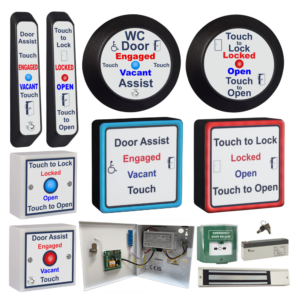
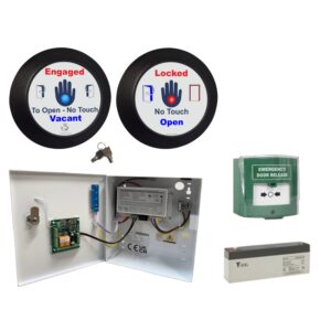
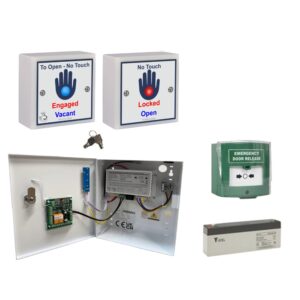
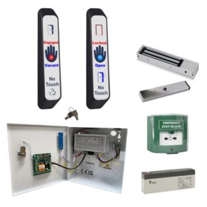
Architrave, round & single gang sensors
🔹Swing door - normally unlocked
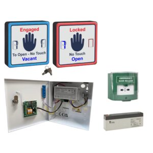
Square sensors:
▪ Sensor Beeps but Doesn’t Lock the System
Solution:
-
Link out the door switch terminals on the control board.
-
If this works, inspect the mag lock reed switch/monitoring wiring and armature plate alignment.
-
Ensure the mag lock provides a normally closed (NC) signal when the door is shut.
- See troubleshooting document for more information.
Note: On RTR mag locks the black & green flying leads connect to the door switch terminals on the WCPCB.
▪ Touch Sensor Doesn’t Beep When Touched
Step-by-step checks (de-power system for 10 seconds after each step):
-
Ensure the sensor is securely mounted—not dangling or held in hand.
-
Check the jumper next to the sensor relay is fitted and making properly.
-
Use a multimeter to check voltage across +V and 0V at the sensor.
- The touch sensor and LEDs use separate supplies – LEDs being lit doesn’t mean the touch sensor side has power.
-
Confirm 0V is in the correct terminal, not the REM terminal.
- Disconnect the sensor from existing cabling and connect it directly to the controller on a short piece of cable to rule out cable issues.
▪ System Locks With No One Inside
Solution:
-
Ensure mag lock contacts are wired into the door switch terminals on the control board.
-
Adjust the potentiometer on the internal touch sensor to switch for 3 – 5 seconds.
-
Reduce the sensitivity of the internal touch sensor, especially if emergency lighting or hand dryers are nearby.
-
Remove any excess cable inside the touch sensor back box.
-
Re-terminate internal touch sensor connections.
- Consider fitting the MULTI-TIMER reset relay.
▪ Automatic door doesn’t open when it should
Solution:
-
Remove the two wires from the C and NO door activation terminals on the control board and join them together.
-
If the door still doesn’t open, the problem lies with the operator—contact the supplier/manufacturer.
▪ System Goes RED But Maglock Doesn’t Engage
Solution:
-
Check the position of the override keyswitch on the external sensor.
-
Ensure the break glass hasn’t been pressed.
-
Inspect the lock fuse.
-
Link out the NC & KS/BG terminals on the control board.
-
If the system works after linking, but your keyswitch and break glass are correctly positioned, there is likely a cable break.
-
-
Use a multimeter to check for voltage at the mag lock.
-
If voltage is present but the lock isn’t engaging, the lock is faulty.
-
▪ Touch Sensor LEDs Aren’t Lit
Solution:
-
Verify that the solid/flashing LED jumper on the control board is in place.
-
If using square sensors, the LED wires should connect to the larger outer PCB (see page 10 of the manual).
-
Use a multimeter to check voltage at the touch sensor LED terminals.
-
The LEDs have a separate power supply from the sensor itself—if the sensor beeps but LEDs don’t light, check for a cable break.
-
-
Remove the sensor from the wall and connect it directly to the control board using a short cable to rule out wiring issues.
▪ Touch Sensor LEDs Flashing (Want Solid Light)
Solution:
-
Change the jumper position on the control board.
▪ Door Re-locks Instantly After Unlocking
Solution:
-
Adjust the potentiometer on the internal touch sensor to switch for 3 – 5 seconds.
-
This may occur if the mag lock contact is going open & closed circuit while the touch sensor is still beeping.
-
Check armature alignment and ensure the door does not judder when opening.
-
If the issue persists, replace the mag lock or install a standard magnetic door contact instead.
▪ Can I Use Multiple Sensors?
Yes!
-
Multiple Door Assist or Touch to Lock/Open sensors can be wired in parallel.
| Weight | 0.070 kg |
|---|---|
| Dimensions | 80 × 65 × 20 mm |
Related products


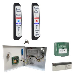
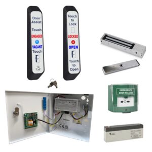
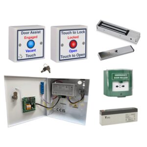
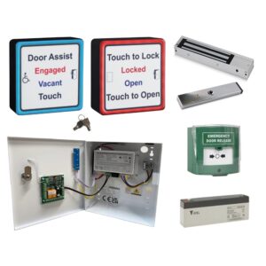
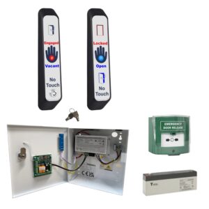
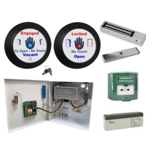
WCKIT Disabled Persons Toilet Locking System
From £312.94 ex VAT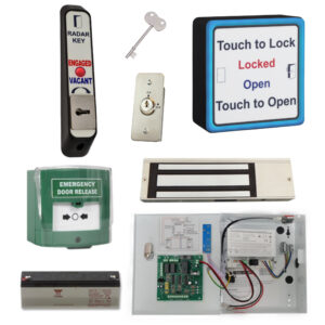

AWCRADAR-KIT Electronic Radar Toilet Door Lock & Key Entry
£625.13 ex VAT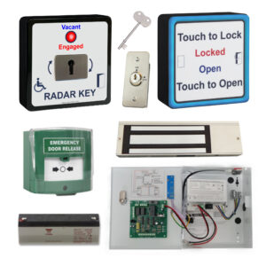
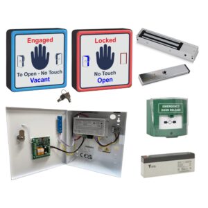
SQWCRADAR-KIT – RADAR toilet door lock for Disabled Toilets
£625.13 ex VAT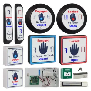
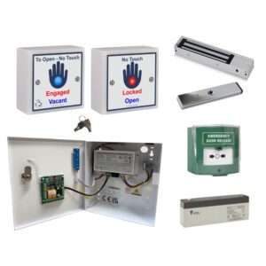
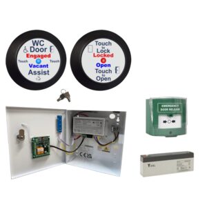
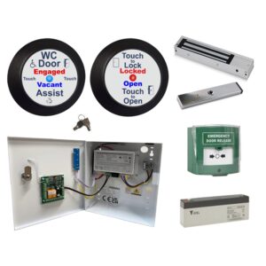
WCKIT-HAND Contactless Toilet Door Locking Kit
From £312.94 ex VAT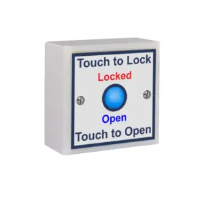


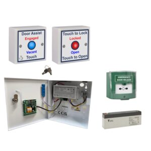
SGWCLOCK Touch to Lock Toilet Door Sensor
£65.98 ex VAT