


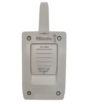
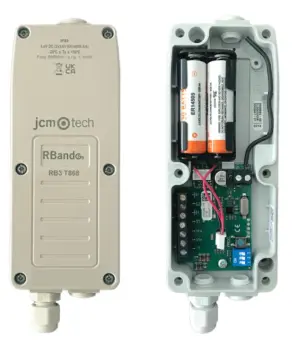
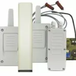
RB3 TGL868 3rd Gen Radioband Safety Edge Transmitter – Advanced Safety & Reliability!
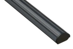
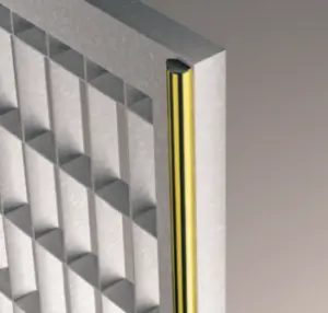
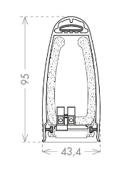
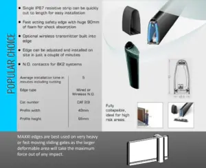
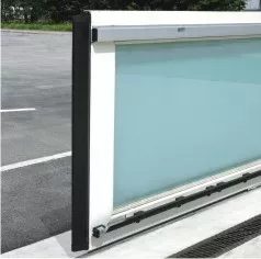
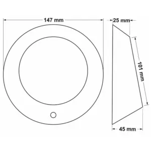
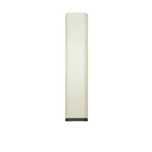
The 3G Radioband Wireless Safety Edge Transmitter is designed for internal roller shutters, providing a slim and compact solution for seamless safety integration.
-
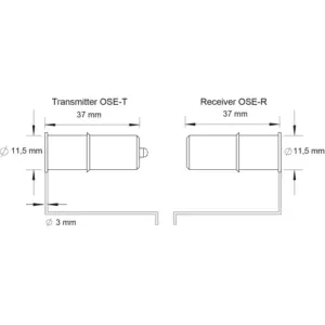
Universal Compatibility – Works with all types of safety edges.
-
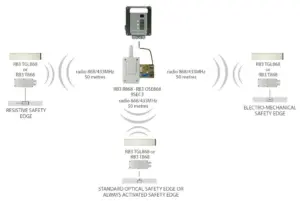
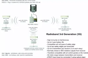
Reliable Wireless Performance – Operates on 3rd generation Radioband technology for stable and interference-resistant communication.
-
Enhanced Signal Stability – Offers high resistance to interference, ensuring consistent operation.
-
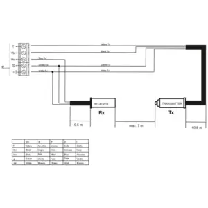
Seamless Integration – Fully compatible with the RB3 R868 3rd generation receiver.
A robust and efficient safety solution for internal roller shutter applications.
Additional information
Weight | 0.18 kg |
- 3G transmitter for optical, resistive and mechanical safety edges.
- Frequency: 868MHz.
- Multi-frequency system: Four 868MHz self-adjusting channels.
- Controls up to 2 safety edges on the same transmitter.
- Program up to 6 transmitters to one receiver (3 per relay).
- No activation signal is required for the optical safety edge - it is always active.
- Approximate battery life: 2 years.
- Nominal range 50 m.
- Power supply: Two 3.6 Vdc ER14500 Li - SOCL lithium batteries.
- Operating temperature: -20ºC to +55ºC.
- Protection degree: IP42.
- Box dimensions: 194.5 x 40 x 20 mm.
Video Player
Media error: Format(s) not supported or source(s) not found
Download File: https://quantek.co.uk/content/uploads/2022/06/Radioband-3G-RB3-Programming.mp4?_=1
Compatible safety edges:
Media error: Format(s) not supported or source(s) not found
Download File: https://quantek.co.uk/content/uploads/2022/06/Radioband-3G-RB3-Programming.mp4?_=2Full Programming Video Tutorial
Pay attention to the LEDs in the transmitter & receiver.
- Change the batteries in the transmitter(s).
- Another transmitter is stored in the memory. Reset the receiver and re-program the transmitters.
- You must first reset the receiver to delete the faulty transmitter out of its memory.
- Then program your transmitter(s) as per the manual or video tutorials.
If safety edge(s) are programmed to relay 1, the R1 LED in the receiver should be OFF in standby and turn ON when an edge is pressed.
If safety edge(s) are programmed to relay 2, the R2 LED should be OFF in standby and turn ON when an edge is pressed.
When the R1 or R2 LED is ON, the corresponding relay output is activated.
If no safety edge is programmed to a relay, the LED will be ON.
If this is the case, the system is working. Check the wiring from the receiver to the gate or door control panel. Refer to the gate/door panel manual or contact the manufacturer.
If this isn’t the case and the R1 or R2 LED is ON in the receiver when an edge isn’t pressed:
- Press the PROG button in the TRANSMITTER for 1 second, the LEDs will flash 9 times. After, the IN1 LED should be off in standby and turn ON when the edge is pressed. Likewise for IN2. If no safety edge is connected to IN2, the IN2 LED will flash.
- If the IN1 or IN2 LED is ON when the edge is not pressed, the dip switches in the transmitter are probably set incorrectly for the type of safety edge being used (or were set incorrectly during programming). Set them correctly in all transmitters, RESET THE RECEIVER, and reprogram one transmitter at a time.
- Note the LEDs turn OFF after 5 minutes to save battery. Press the PROG button again for 1 second to turn them back ON.
- If the dipswitches are set correctly but the IN1 or IN2 LED is still ON when the edge is not pressed, this indicates a fault with the edge. See next section.
- If the LEDs in the transmitters are all behaving as they should, but the R1 or R2 LEDs are ON in the receiver when no edge is pressed, run the CHECK procedure to test the signal. (Page 18 in the manual). If poor, ensure there are no metal objects between transmitters & receiver that they’re installed in the same orientation where possible. Antennas can be purchased for the receiver if required.
Assuming you’re using resistive safety edges:
- Disconnect the safety edge and put an 8K2 resistor across S1 & GND terminals.
- Set the transmitter dipswitches for a resistive edge. (1-OFF, 2-ON, 3-OFF)
- Reset the receiver and re-program the transmitter.
- If this works, the fault is with the safety edge.
- Disconnect the safety edge from the transmitter and put an 8K2 resistor in its place, if the system works normally, the issue is the safety edge.
- On rare occasions, even though a safety edge measures the correct resistance with a multi-meter, there can still be an issue with it, such as a small nick in the rubber.
- If using 3 wire optical edges, you must connect the ATEST to the control panel. The ATEST signal is used to power up and down the optical eyes for the door movement. Dipswitch 2 must be OFF in the receiver. Refer to the door or gate control panel manual or contact the manufacturer.
- Alternatively, use OSE-S 7502 optical eyes. No activation signal is required.
Batteries should last 1-2 years
- If the batteries are draining quickly, the transmitter will need replacing.
- If out of warranty, please purchase another.
- If in warranty, please send us pictures of the transmitter in situ. (With the cover on and off).
- If transmitter has been installed correctly and is in a suitable condition, we will give you a returns number to return the item for replacement.
- Relay 1 – CS1 & C1. Relay 2 – CS2 & C2.
- Relay output may need wiring in series with the photocell or stop button.
- Relay 1 – C1 & BS1. Relay 2 – C2 & BS2.
- The memory is full. It is possible to program 3 safety edges per relay.