OSE-S 7502 Optical Sensing Edge
£33.30 ex VAT
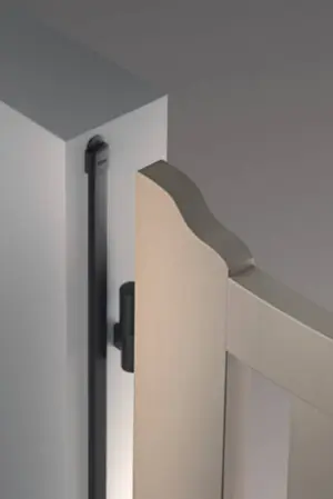
Always active optical sensing edge
The OSE-S 7502 is an always-active optical sensing edge designed for reliable protection in automated gates and doors. Fully compatible with the RadioBand 3G system, it uses optical sensors installed at each end of a rubber safety edge strip (sold separately) to create a beam across the edge. When the edge is compressed, the beam is broken, instantly stopping and reversing the door or gate to prevent damage or injury.
With intelligent light beam control, the system reduces power consumption by up to 20 times and requires no activation signal, ensuring continuous, efficient operation.
Key Features:
- Always-active optical safety edge
- Compatible with RadioBand 3G systems (RB3 T868, RB3 TGL & RB3 R868)
- Beam interruption detection for fast response
- Stops and reverses gates/doors on impact
- Up to 20x lower power consumption
- No activation signal required
- Additional control cable for beam management
- Suitable for automatic gates and industrial doors
| Technology: | Optical Sensing Edge |
| Cable Length: | 10.5 / 0.5 m |
| Connection Type: | Cable, w/o plug |
| Supply Voltage: | DC 4-28 V |
| Range: | 6 m |
| Output: | OSE 4-Wire |
| Additional Functions: | Suitable for JCM Radioband 3G |
▪ After programming the door or gate won't close
If safety edge(s) are programmed to relay 1, the R1 LED in the receiver should be OFF in standby and turn ON when an edge is pressed.
If safety edge(s) are programmed to relay 2, the R2 LED should be OFF in standby and turn ON when an edge is pressed.
When the R1 or R2 LED is ON, the corresponding relay output is activated.
If no safety edge is programmed to a relay, the LED will be ON.
If this is the case, the system is working. Check the wiring from the receiver to the gate or door control panel. Refer to the gate/door panel manual or contact the manufacturer.
If this isn’t the case and the R1 or R2 LED is ON in the receiver when an edge isn’t pressed:
- Press the PROG button in the TRANSMITTER for 1 second, the LEDs will flash 9 times. After, the IN1 LED should be off in standby and turn ON when the edge is pressed. Likewise for IN2. If no safety edge is connected to IN2, the IN2 LED will flash.


- If the IN1 or IN2 LED is ON when the edge is not pressed, the dip switches in the transmitter are probably set incorrectly for the type of safety edge being used (or were set incorrectly during programming). Set them correctly in all transmitters, RESET THE RECEIVER, and reprogram one transmitter at a time.
- Note the LEDs turn OFF after 5 minutes to save battery. Press the PROG button again for 1 second to turn them back ON.
- If the dipswitches are set correctly but the IN1 or IN2 LED is still ON when the edge is not pressed, this indicates a fault with the edge or a twist or depression in the rubber.
- If the LEDs in the transmitters are all behaving as they should, but the R1 or R2 LEDs are ON in the receiver when no edge is pressed, run the CHECK procedure to test the signal. (Page 18 in the manual). If poor, ensure there are no metal objects between transmitters & receiver that they’re installed in the same orientation where possible. Antennas can be purchased for the receiver if required.
▪ How do I set the dipswitches in the Radioband 3G Transmitter & Receiver
Answer:
All dipswitches must be set before programming, otherwise you will need to reset the receiver.
- Transmitter: All 3 in the OFF position.
- Receiver: 2 ON position if not connecting autotest, 2 OFF position if connecting autotest to activate the eyes. 1, 3 & 4 can be set as required, refer to page 8 of manual.
▪ Can I connect the eyes directly to the control panel
Answer:
No, they only work with Radioband 3G.
Transmitters: RB3 T868 | RB3 TGL868
Control panel kits: M8 RB3 KIT | ML8 RB3 KIT | KEEROLL RB3 ALARM KIT
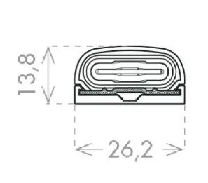
Rubber: OSE-RP
| Weight | 0.2 kg |
|---|---|
| Dimensions | 10.5 × 0.5 mm |
Related products
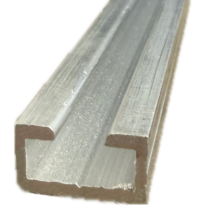
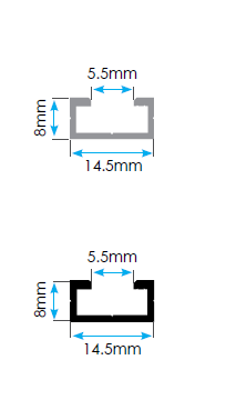
OSE-AR Aluminium Optical Safety Edge Mounting Rail
From £9.34 ex VAT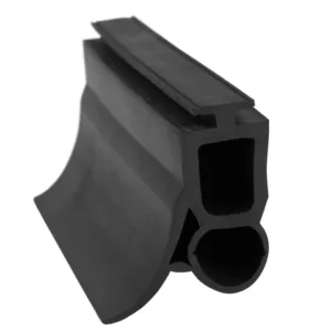
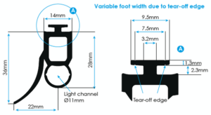
OSE-RP Optical Safety Edge Rubber Profile
From £13.64 ex VAT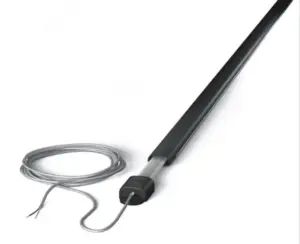
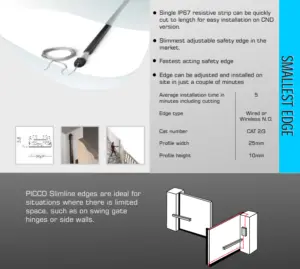
8K2 PICCO Small Profile Resistive Safety Edges
From £79.44 ex VAT

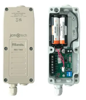
RB3 TGL868 3rd Gen Radioband Safety Edge Transmitter
£55.79 ex VAT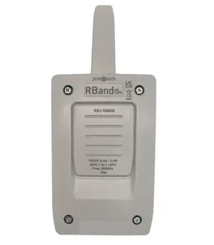
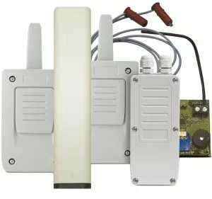
RB3 R868 3rd Generation Radioband Safety Edge Receiver
£55.79 ex VAT