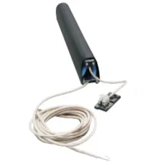
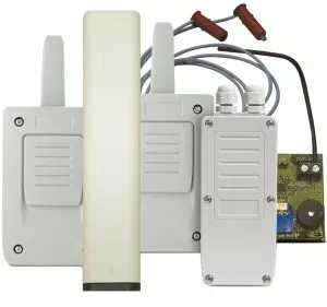
RB3 T868 3rd Generation Safety Edge Transmitter
£55.79 ex VAT
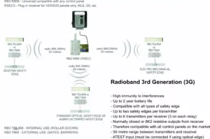
3rd Generation Transmitter For Safety Edge
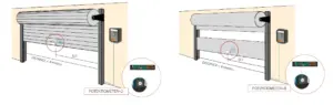
- 3G transmitter for optical, resistive and mechanical safety edges.
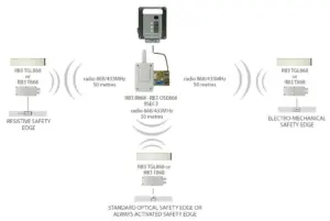
- Frequency: 868MHz.
- Multi-frequency system: Four 868MHz self-adjusting channels.
- Controls up to 2 safety edges on the same transmitter.
- Up to 6 transmitters can be programmed onto one receiver (3 on each relay)
- No activation signal is required for the optical safety edge – it is always active.
- Approximate battery life: 2 years.
- Nominal range 50 m.
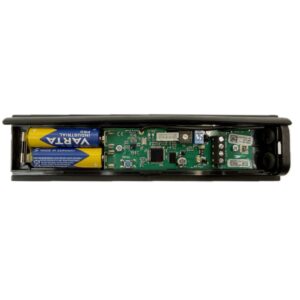
- Power supply: Two 3.6 Vdc ER14500 Li – SOCL lithium batteries.
- Operating temperature: -20ºC to +85ºC.
- Protection degree: IP65.
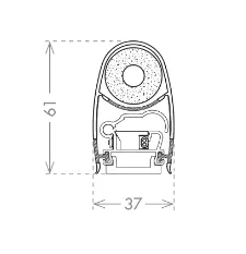
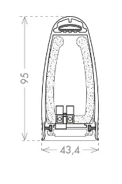
- Box dimensions: 151 x 60 x 23 mm.
Compatible receiver:
Compatible safety edges:
▪ Most programming issues can be solved by watching the video tutorial
▶Full Programming Video Tutorial
Pay attention to the LEDs in the transmitter & receiver.
▪ 4 beeps every 5 seconds from receiver/control panel
Solution:
- Change the batteries in the transmitter(s).
- Another transmitter is stored in the memory. Reset the receiver and re-program the transmitters.
▪ Replacing an old or faulty transmitter
Procedure:
- You must first reset the receiver to delete the faulty transmitter out of its memory.
- Then program your transmitter(s) as per the manual or video tutorials.
▪ After programming the system, the gate or door won’t close/open
Solution:
If safety edge(s) are programmed to relay 1, the R1 LED in the receiver should be OFF in standby and turn ON when an edge is pressed.
If safety edge(s) are programmed to relay 2, the R2 LED should be OFF in standby and turn ON when an edge is pressed.
When the R1 or R2 LED is ON, the corresponding relay output is activated.
If no safety edge is programmed to a relay, the LED will be ON.
If this is the case, the system is working. Check the wiring from the receiver to the gate or door control panel. Refer to the gate/door panel manual or contact the manufacturer.
If this isn’t the case and the R1 or R2 LED is ON in the receiver when an edge isn’t pressed:
- Press the PROG button in the TRANSMITTER for 1 second, the LEDs will flash 9 times. After, the IN1 LED should be off in standby and turn ON when the edge is pressed. Likewise for IN2. If no safety edge is connected to IN2, the IN2 LED will flash.


- If the IN1 or IN2 LED is ON when the edge is not pressed, the dip switches in the transmitter are probably set incorrectly for the type of safety edge being used (or were set incorrectly during programming). Set them correctly in all transmitters, RESET THE RECEIVER, and reprogram one transmitter at a time.
- Note the LEDs turn OFF after 5 minutes to save battery. Press the PROG button again for 1 second to turn them back ON.
- If the dipswitches are set correctly but the IN1 or IN2 LED is still ON when the edge is not pressed, this indicates a fault with the edge. See next section.
- If the LEDs in the transmitters are all behaving as they should, but the R1 or R2 LEDs are ON in the receiver when no edge is pressed, run the CHECK procedure to test the signal. (Page 18 in the manual). If poor, ensure there are no metal objects between transmitters & receiver that they’re installed in the same orientation where possible. Antennas can be purchased for the receiver if required.
▪ How to confirm if a safety edge is faulty
Answer: Assuming you’re using resistive safety edges:
- Disconnect the safety edge and put an 8K2 resistor across S1 & GND terminals.
- Set the transmitter dipswitches for a resistive edge. (1-OFF, 2-ON, 3-OFF)
- Reset the receiver and re-program the transmitter.
- If this works, the fault is with the safety edge.
▪ My safety edge is measuring 8K2 Ohms but is showing as activated/pressed
Answer:
- Disconnect the safety edge from the transmitter and put an 8K2 resistor in its place, if the system works normally, the issue is the safety edge.
- On rare occasions, even though a safety edge measures the correct resistance with a multi-meter, there can still be an issue with it, such as a small nick in the rubber.
▪ What do the dip-switches in the receiver do?
Answer:
- For most installations they can all be left in the off position.
- If you need to change them, they must be set before programming the transmitters, otherwise you will need to reset the receiver and re-program the system.

▪ Battery life is poor (optical edge)
Answer:
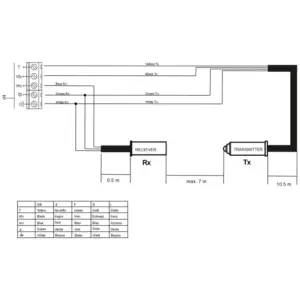
- If using 3 wire optical edges, you must connect the ATEST to the control panel. The ATEST signal is used to power up and down the optical eyes for the door movement. Dipswitch 2 must be OFF in the receiver. Refer to the door or gate control panel manual or contact the manufacturer.
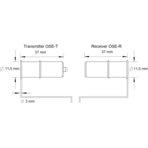
- Alternatively, use OSE-S 7502 optical eyes. No activation signal is required.
▪ Battery life is poor (resistive or mechanical edge)
Answer: Batteries should last 1-2 years
- If the batteries are draining quickly, the transmitter will need replacing.
- If out of warranty, please purchase another.
- If in warranty, please send us pictures of the transmitter in situ. (With the cover on and off).
- If transmitter has been installed correctly and is in a suitable condition, we will give you a returns number to return the item for replacement.
▪ How do I connect the receiver to a normally closed stop or photocell input on the control panel?
Answer:
- Relay 1 – CS1 & C1. Relay 2 – CS2 & C2.
- Relay output may need wiring in series with the photocell or stop button.
▪ How do I connect the receiver to an 8K2 resistive safety edge input on the control panel?
Answer:
- Relay 1 – C1 & BS1. Relay 2 – C2 & BS2.
▪ 1 long & 9 shorter beeps from the receiver when trying to program a transmitter
Answer:
- The memory is full. It is possible to program 3 safety edges per relay.
| Weight | 0.18 kg |
|---|---|
| Dimensions | 151 × 60 × 23 mm |
Related products
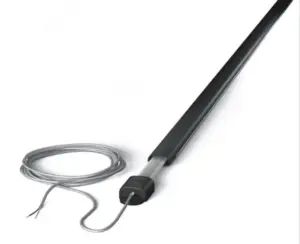
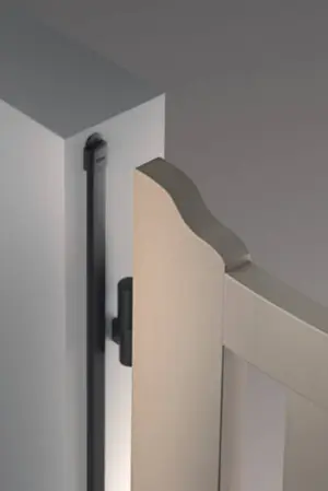
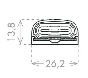
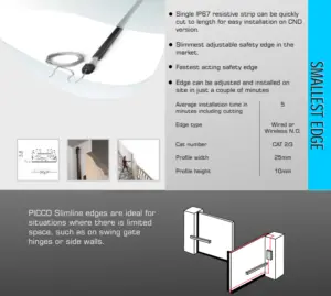
8K2 PICCO Small Profile Resistive Safety Edges
From £79.44 ex VAT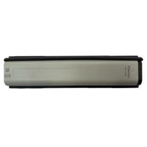
RS3 TGL868 Impact Detector With No Safety Edge – RadioSens3
£55.79 ex VAT

CCE 8K2 COMPACT Resistive Safety Edges
From £68.76 ex VAT
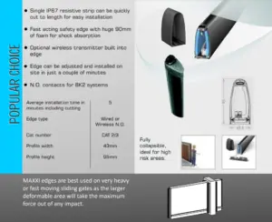
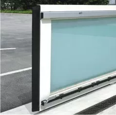
8K2 MAXXI Resistive Sliding Gate Safety Edge
From £126.28 ex VAT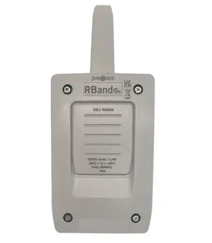
RB3 R868 3rd Generation Radioband Safety Edge Receiver
£55.79 ex VAT