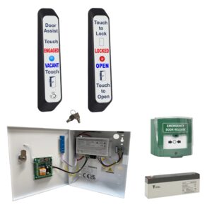
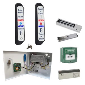
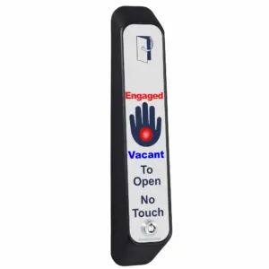
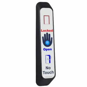
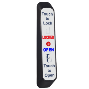
AWCEURO Architrave Toilet Door Indicator Open/Lock
From £65.98 ex VAT
Architrave toilet door indicator.
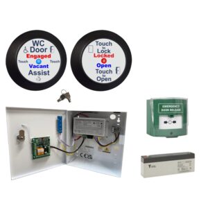
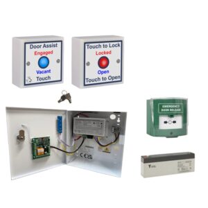
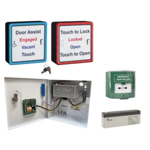
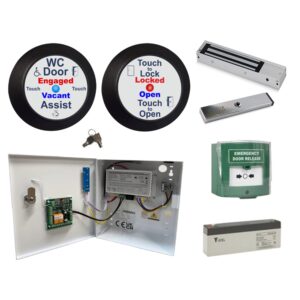
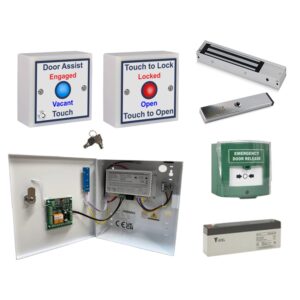
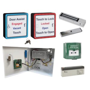
Our toilet door indicator has padlock symbols to signify the lock status, helping alleviate language issues. Our disabled toilet locking systems are the system of choice due to its simple, easy to use, reliable and adaptable design. As used in the House of Commons, House of Lords, Heathrow and Gatwick airports, plus many more!
The switches are great for people who struggle with dexterity, because no physical press is needed. The red and blue status indicators have also been chosen to aid people with visual impairments. The entire label is protected by an antimicrobial agent, meaning 99.9% of germs are destroyed, making them a very clean switch!
Features:
- The units are powered by 12-24Vdc.
- Switching red & blue LEDs to show engaged or vacant status
- Key switch on all external sensors for emergency entry
- Anti-prank contact to prevent misuse
- Timed clean output for auto door activation
How does it work?
- When the door is unlocked you can enter manually or operate the external sensor for assisted entry.
- Once inside the cubicle, activate the internal sensor which will lock the door.
- When you are ready to exit, activate the internal sensor again to unlock the door with assisted exit.
To discuss this product in more detail, or to explore bespoke labels or system options, please contact us. Our team will be happy to assist with technical guidance, custom requirements, or project specifications.
- 12-28Vdc
- Designed to overcome language barriers
- 4 position sensitivity adjustment (Touch to hands free)
- Entire label is sensitive
- Red & blue LED indicators to show lock status
- Sounder on activation
- Reinforced nylon housing
- Scratch resistant antimicrobial acrylic label with Steritouch, kills 99.9% of germs!
- IP65 rated
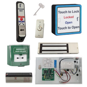
The system can be configured in many ways, below are the 3 basic formats.
- 2 sensor operation: Door unlocked, enter manually or operate sensor for assisted entry, touch internal sensor to lock the door, touch again to unlock the door with assisted exit.
- 3 sensor operation: Door unlocked, enter manually or operate sensor for assisted entry, touch internal sensor to lock the door, touch again to unlock door, exit manually or operate internal door assist sensor to gain assisted exit.
- Secure access: Door locked, a proximity token/card is required to gain manual or assisted entry, touch internal sensor to lock the door, touch again to unlock door, exit manually or with assisted exit.
🔒 Sensor Beeps but Doesn’t Lock the System
-
Link out the door switch terminals on the control board.
-
If this works, check:
-
Maglock reed switch wiring
-
Monitoring cable
-
Armature plate alignment
-
-
The maglock must provide a normally closed signal when the door is shut.
🚫 Touch Sensor Doesn’t Beep When Touched
After each step, power down the system for 10 seconds before restarting.
-
Ensure the sensor is securely mounted—not dangling or held in hand.
-
Check the jumper next to the sensor relay is fitted and seated properly.
-
Use a multimeter to check voltage across +V and 0V at the sensor.
-
Confirm 0V is in the correct terminal, not the REM terminal.
-
Bypass cabling by wiring the sensor directly to the power supply using a short lead.
🔐 System Locks With No One Inside
-
Confirm the maglock contacts are wired to the door switch terminals on the control board.
-
Set the potentiometer on the internal sensor for a 3–5 second delay.
-
Reduce sensor sensitivity, especially near emergency lights or hand dryers.
-
Remove excess cable from the sensor’s back box.
-
Re-terminate all sensor connections.
🚪 Automatic Door Doesn’t Open
-
Remove the two wires from C and NO terminals on the control board.
-
Touch them together:
-
If the door still doesn’t open, the issue is with the door operator—contact the supplier.
-
🔴 System Goes RED But Maglock Doesn’t Engage
-
Check the override keyswitch on the external sensor.
-
Ensure the break glass hasn’t been pressed.
-
Inspect the lock fuse.
-
Link out the NC & KS/BG terminals on the control board:
-
If the system works with the link in place, and the keyswitch & break glass are in correct positions, there may be a cable fault.
-
-
Use a multimeter to check for voltage at the maglock.
-
If voltage is present but the lock isn’t engaging, the lock is faulty.
-
💡 Touch Sensor LEDs Aren’t Lit
-
Check the LED jumper (solid/flashing) on the control board is in place.
-
For square sensors, ensure LED wires are connected to the larger outer PCB (see manual p.10).
-
Use a multimeter to test voltage at the LED terminals:
-
The sensor and LEDs use separate supplies—beeping doesn’t mean LEDs have power.
-
-
Bypass any cabling issues by wiring the sensor directly to the control board with a short cable.
✳️ Touch Sensor LEDs Flashing (Want Solid Light)
Adjust the LED jumper position on the control board.
🔁 Door Re-locks Instantly After Unlocking
-
Adjust the internal sensor delay to 3–5 seconds using the potentiometer.
-
Check if the maglock contact is flickering while the sensor is still beeping.
-
Ensure the armature plate is aligned and the door isn’t juddering on opening.
-
Replace the maglock or use a standard magnetic door contact if needed.
➕ Can I Use Multiple Sensors?
-
Yes!
-
You can install multiple internal or external touch sensors.
-
Just wire them in parallel.
-
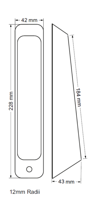
| Weight | 0.14 kg |
|---|---|
| Dimensions | 230 × 42 × 43 mm |
Related products


WCKIT Disabled Persons Toilet Locking System
From £312.94 ex VAT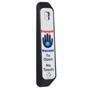

AWCHASS-K Contactless Toilet Door Indicator Sensor
£85.27 ex VAT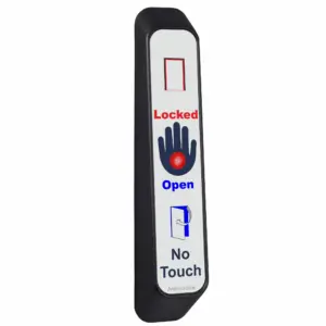
AWCHLOCK Contactless Toilet Door Sensor
£65.98 ex VAT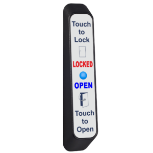
AWCLOCK Architrave Antimicrobial Touch to Lock Toilet Sensor
£65.98 ex VAT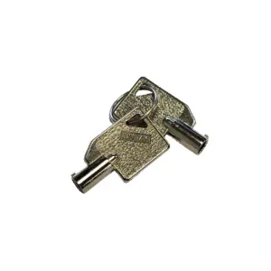

Emergency Door Access Override Keys – WCKEY 102
£4.41 ex VAT