


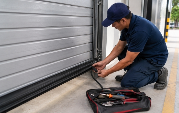
A safety edge that fails on site rarely announces itself clearly. The door might reverse for no obvious reason, or prevent the gate from moving when there is no obstruction. Working out if the fault sits in the rubber profile, the cable run, the controller or Radioband settings can turn a five-minute job into an hour of guesswork without a structured approach, particularly on swing doors and loading bay installations where cable fatigue and vibration are constant background factors.
Safety edges are one of the few components on an automated door or gate where a fault genuinely cannot be left for later. A bypassed or malfunctioning edge removes the obstruction detection the system depends on, which creates a direct injury risk and puts the installation out of compliance with the safety standards it was certified against.
This checklist walks through the fault-finding process in the order most installers will actually use it: visual inspection of the profile and cable run, resistance testing to narrow down mechanical or electrical damage, controller or Radioband configuration checks, and a full functional test before the system goes back into service. If the fault is a safety edge not working straight after installation or a recurring problem that has developed over months of use, working through these steps in sequence will usually identify the cause faster than testing components at random.
What Is a Safety Edge and Why Does It Fail?
A safety edge is a pressure-sensitive strip fitted to automated doors, gates, or roller shutters. When it comes into contact with an obstruction, it signals the operator to stop and reverse movement. This makes it one of the most important safety devices in automated access systems.
Most safety edge failures fall into three categories:
- Mechanical damage
- Wiring faults
- Controller or Radioband configuration issues
Successful safety edge troubleshooting begins by determining which category the fault belongs to before carrying out further testing.
Step 1: Carry Out a Visual Inspection
Before testing electrical components, perform a thorough visual inspection. Many cases of a safety edge not working can be traced to physical damage that is immediately visible.
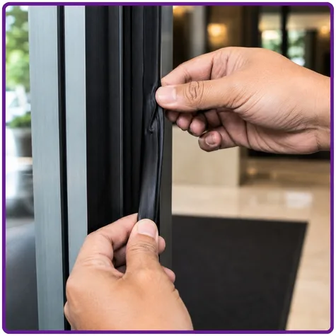
Check the Rubber Profile
Inspect the entire length of the safety edge profile for:
- Cuts
- Compression
- Deformation
- Splits or tears
A crushed profile can affect the internal resistance wire, while even minor damage can allow moisture ingress. Moisture may cause partial short circuits, false triggering, or complete failure.
Check the Mounting
Confirm that the safety edge:
- Is correctly seated in its retaining channel
- Has not shifted position
- Maintains full contact across the protected area
An incorrectly positioned edge may fail to detect obstructions effectively.
Check the Cable Run
Inspect the cable from the safety edge to the controller for:
- Pinching
- Sharp bends
- Fraying
- Damage around hinges and pivot points
Cable fatigue near hinges is a common cause of intermittent or complete failure, particularly on swing door installations where the cable flexes during every cycle.
Step 2: Test the Resistance Values
Every resistive safety edge is designed to operate within a specified resistance range. Resistance testing should always be part of your safety edge troubleshooting process.
How to Test
- Disconnect the safety edge from the controller.
- Measure resistance across the two conductors using an ohmmeter.
- Compare the reading with the manufacturer’s specification.
The reading should be 8.2kΩ ± 5% to 10%
Understanding the Results
Open Circuit
Likely Cause:
- Broken internal resistance wire
- Cable fatigue
- Physical damage
Solution:
- Replace the safety edge.
Short Circuit
Likely Cause:
- Moisture ingress
- Direct cable short
Solution:
- Dry the edge and retest.
- Replace the edge if the short remains.
Reading Within Tolerance
Likely Cause:
- Controller configuration issue
- Fault elsewhere in the circuit
Solution:
- Continue troubleshooting at the controller.
Reading Outside Tolerance
Likely Cause:
- Incorrect termination resistors
- Installation error
Solution:
- Verify resistor values against manufacturer specifications.
Step 3: Inspect Wiring and Terminations
Wiring faults are among the most common causes of a safety edge not working correctly, especially on new installations or after controller replacement.
Common Wiring Faults
Loose Connections
Check all terminal connections for tightness.
High-cycle applications such as loading bay doors can gradually loosen terminal screws due to vibration.
Intermittent Faults
If the issue appears only when the door moves, suspect cable fatigue at flex points first.
Step 4: Check Controller/Radioband Input Settings
After confirming the edge and wiring are functioning correctly, verify that the controller or Radioband is configured to recognise the safety edge input.
Key Controller Checks
Safety Edge Input Enabled
Ensure the safety edge input has not been bypassed.
Some controllers use:
- Jumpers
- DIP switches
- Software settings
that can disable the input during testing.
Correct Edge Type Selected
Verify the controller is configured for the correct device type:
- Resistive
- OSE Optical
- Electromechanical
- Wireless
Using the wrong input type prevents correct signal interpretation.
Radioband checks
If using JCM Tech wireless Radioband:
- Check the jumper or dipswitches are set correctly in the transmitter.
- Reset the receiver and re-program one transmitter at a time.
- Watch our programming video and view troubleshooting on our website.
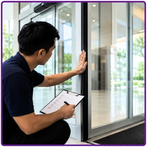
Step 5: Perform a Full Functional Test
After repairs or adjustments, carry out a complete system test before returning the installation to service. This is required under BS EN 16005 and related standards.
Functional Test Procedure
Test the Entire Edge
Apply pressure along the full length of the safety edge and confirm:
- Stop function operates correctly
- Reverse function activates
- All contact points respond
Test All Speeds
Where applicable, test at:
- Slow speed
- Fast speed
Verify Reset Behaviour
Confirm the system returns to normal operation after the obstruction is removed, unless the controller is designed to latch faults.
Record Results
Document:
- Test outcomes
- Adjustments made
- Compliance checks
This documentation supports service records, audits, and insurance requirements.
Recurring Safety Edge Faults
If the same fault repeatedly occurs, the problem is often systemic rather than accidental.
Repeated Cable Fatigue at Hinges
Symptoms
- Intermittent operation
- Fault returns after repair
Solution
- Install a dedicated flex loop
- Use spiral wrap protection
- Fit a hinge cable connector kit
- Ensure sufficient cable slack for full movement
- Make the safety edges wireless with Radioband 3G
Moisture Ingress in Outdoor Installations
Symptoms
- Recurring short circuits
- Faults after rain or condensation
Solution
- Seal cable entry points
- Use self-amalgamating tape or suitable mastic
- Confirm the safety edge is rated for outdoor use
Nuisance Tripping
Symptoms
- Trigger signals with no obstruction present
Possible Causes
- Partial cable short
- Internal profile compression
Solution
- Conduct a full wiring inspection
- Replace damaged profiles
Compliance and Standards
Professional safety edge troubleshooting should always consider regulatory compliance. The most relevant standards include:
BS EN 16005
Power-operated pedestrian doorsets, including safety requirements for sensors and safety edges.
BS EN 12453
Safety requirements for industrial, commercial, and garage doors and gates.
BS EN 13241
Performance and safety requirements for industrial, commercial, garage, and pedestrian doors used as building products.
Machinery Directive (2006/42/EC Retained in UK Law)
Applies to many automated gate systems and requires hazards to be controlled using appropriate safety measures, including safety edges where necessary.
Important: If a safety edge is not working and has been bypassed, the installation is no longer compliant. Site managers or facilities teams should be informed in writing until the fault is resolved.
Quick Reference: Safety Edge Troubleshooting Checklist
Visual Inspection
- Check the rubber profile for cuts, splits, or compression.
- Confirm the edge is correctly seated in the retaining channel.
- Inspect the cable run for pinching, fraying, or hinge fatigue.
Resistance Test
- Disconnect the edge from the controller.
- Measure resistance at the edge end.
- Compare readings to the manufacturer’s specification.
- Check for open circuits, short circuits, or out-of-range values.
- Verify termination resistor values.
Wiring Audit
- Tighten all terminal connections.
- Inspect cables for pinch points and damage.
Controller Configuration
- Confirm the safety edge input is enabled.
- Verify the correct edge type is selected.
- Review fault codes and error logs.
Functional Testing
- Test stop and reverse functions along the full length of the edge.
- Confirm correct reset behaviour after the obstruction is removed.
- Use a 50mm test cylinder where required by the relevant standard.
- Record all test results and retain documentation for compliance purposes.
Conclusion
Safety edge troubleshooting is most effective when approached systematically. By following a structured process that includes visual inspection, resistance testing, wiring checks, controller verification, and functional testing, installers can identify and resolve faults efficiently and safely.
Whether a safety edge not working issue occurs immediately after installation or develops over time, the root cause typically falls into one of three categories: physical damage, wiring faults, or configuration errors. Recurring faults often indicate underlying issues such as poor cable routing, inadequate weatherproofing, or incorrect system setup that require permanent corrective action.
Compliance with BS EN 16005, BS EN 12453, and related standards remains essential. Any installation operating with a non-functional safety device should be documented and reported until the fault has been fully resolved. For products, technical support, and expert advice on safety edge systems and access control components, contact the Quantek team.