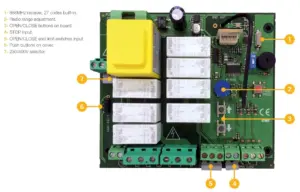
i20 Three-Phase Control Panel
£207.06 ex VAT
Three-Phase Control Panel From JCM Tech
The i20 is a premium 3-phase control panel engineered for demanding industrial environments. Designed to work with a wide range of three phase motors, it’s ideal for applications including roller doors, folding doors, and high-speed doors.
Built with ease of use in mind, the i20 features intuitive onboard programming buttons and a straightforward setup process, allowing for quick configuration and efficient operation. Its advanced connectivity and wide range of safety inputs make it a dependable solution for modern automated door systems.
Key Features:
- Suitable for all types of industrial doors, including roller, folding, and fast doors
- Compatible with a wide range of three-phase motors (up to specified maximum power)
- Simple programming via onboard buttons
- Easy and intuitive operational mode adjustment
- Dedicated connector for digital limit switches (ELEKTROMATEN & KOSTAL)
- Supports optical and resistive safety edges
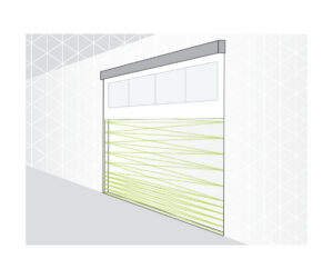
- Safety light curtain input
- Photocell/safety beam input
- Emergency stop button input
- Keyswitch and pushbutton input compatibility
- 24 Vac/dc outputs (max. 700mA)
- Door open and closed status output
- Plug-in connectors for safety edge receiver (RSEC3) and remote control receiver (STICK) to minimise wiring
- Autoclose function with adjustable timer (3–60 seconds)
- Designed for reliable, safe, and efficient industrial door control
- Three-phase or single phase control panel for industrial doors.
- Power supply/ Max. Power of motor 230v/1200W and 400v/2200W
- Suitable for mechanical or digital limit switches
- Safety edge input (optical or resistive)
- Photocell input
- Emergency stop input
- Keyswitch/push button input
- Partial open input
- Door open & closed status outputs
- Motor brake output
- Flashing light output
- Deadman or push to run open & close selectable by dipswitch. If you wish to run the door in deadman and also want to use remote transmitters, please contact us before ordering.
- Autoclose selectable by dipswitch
- Connector for STICK receiver for remote controls
- Connector for RSEC receiver for wireless safety edge
- Input/output active indicator for diagnostics
- Independent outputs 24v AC and 24v DC, max. 700 mA.
- Water tightness: IP65
- Temp (ºC): -20 - +55
- Dimensions: 225 x 305 x 126mm
▪ Door is running past its open and/or close position
Solution:
- The open and close position can only be set via the panel if there are digital limits/encoder connected. If not, mechanical limits must be wired into the control panel and be adjusted properly at the motor.
▪ Door won’t close and/or open
Active safety devices:
Red LEDs next to the inputs indicate if that input is active. For example, if the LED next to the photocell input is lit, it indicates a fault with the photocell which is stopping the door from closing.
- If fitted, check the photocell is clean, aligned properly and that the cables are undamaged. If not fitted, check the terminals are linked.
- If fitted, check the safety edge is in working order and the cable isn’t damaged. If not fitted, check the terminals are linked with an 8K2 resistor.
- If fitted, check that the emergency stop button hasn’t been pressed and check the cable to the emergency stop button is undamaged. If not fitted, check the terminals are linked.
- Reprogram the door movement, especially after fitting an optical safety edge or light curtain.
Limit switches:
- Ensure the dipswitch is set correctly for the type of limit switch you’re using.
- Mechanical limits:
- The LIM.OP. LED should only be lit when the door is at its open limit. The LIM.CL. LED should only be lit when the door is at its close limit.
- If this is not the case, link out all 3 limit switch terminals and turn on dipswitch 2 (DM OPEN) and dipswitch 3 (DM CLOSE).
- Check that the door opens & closes in deadman.
- If it does, check limit switch wiring and adjust the limits at the motor if necessary.
- Reprogram the door movement.
- Digital limits (Encoder):
- Reprogram the door movement.
Other things to check:
- If the control panel is clicking when a remote or button is pressed, check the motor wiring and condition.
- Check there is power to the control panel
- Check the fuse.
▪ How do the remote controls work?
Answer:
- The STICK receiver uses one channel as a START input operating sequentially (open – stop – close – stop, etc) and assumes appropriate safety is fitted.
- If you want to use the remotes in a different configuration or with the panel in deadman, please order the VERSUS-PROG or contact us before ordering so we can pre-program the control panel inputs. You will also need deadman transmitters.
▪ Need more help?
See page 16 of the manual for more fault indicators.
Receiver: STICK. The receiver uses one channel as a START input operating sequentially (open - stop - close - stop, etc) and assumes appropriate safety is fitted. If you wish to use a different configuration please contact us before ordering.
Handheld remotes compatible with STICK: GO-MINI | GO2 | MUV2 | GO4 | MUV4
Wall transmitters compatible with STICK: GO-PUSH2 | GO-KEY | KEEPAD | KEEPUSH
Wired buttons/keyswitches: RS | KEY2 | ESB
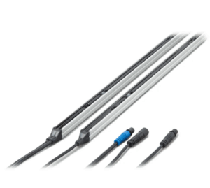
Wireless safety edge: RSEC3 | RB3 TGL868 | OSE-S 7502 | Any resistive safety edge
Wired safety edge: 3 wire optical edge | Any resistive safety edge
Safety photocells: CP-PC180 | CP-PC180B | CP-PC180AV | CP-PC180B-AV | IR8000
Safety light curtain: GRIDSCAN/PRO-2500
| Weight | 2.40 kg |
|---|---|
| Dimensions | 225 × 305 × 126 mm |
Related products
GRIDSCAN/PRO Safety Light Curtains
From £278.95 ex VAT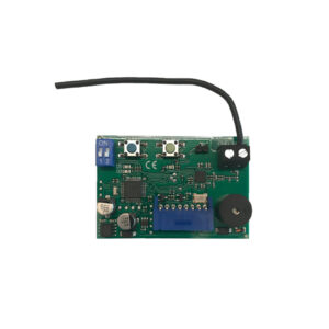
RSEC3 Plug in safety receiver
£49.95 ex VAT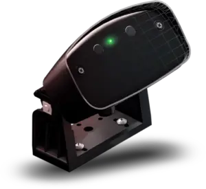
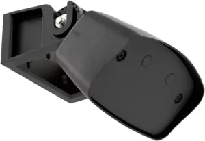
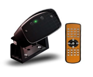
Hotron HR ROBUS Industrial Door Sensor
£119.69 ex VAT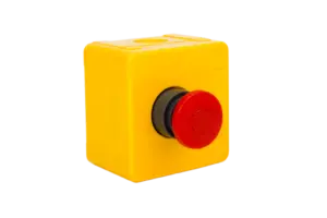

ESB Emergency Stop Button Switch
Original price was: £18.56.£11.20Current price is: £11.20. ex VAT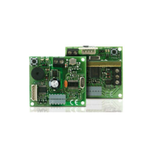
STICK30 & STICK500 868MHz Plug-In Receiver Cards – Reliable & Secure Wireless Control
From £36.09 ex VAT